Export Clamp to STEP and IGES
Clamps create in Guideline can be exported in STEP and IGES format, ready to be imported back in CAD (for seats modeling) or CAM (for cam path design).
For clamp export in NX see Guideline-NX interoperability #2: ON-LINE
For clamp export in CATIA see Export clamps in .CATProduct format
EXAMPLE VIDEOS
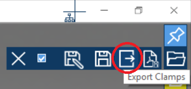
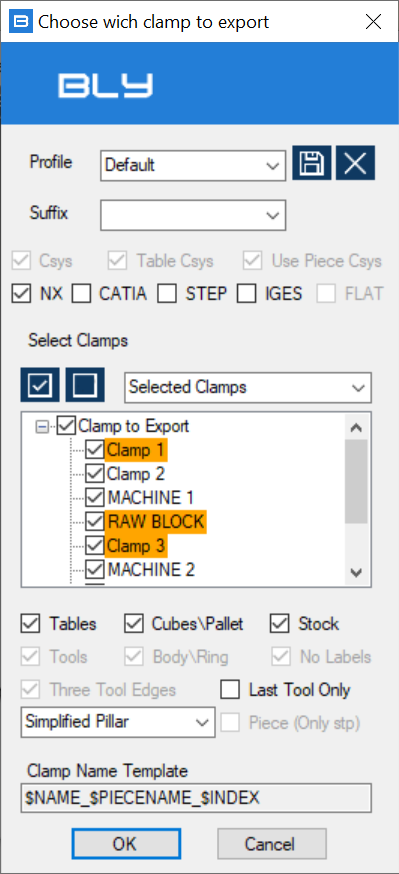
To enter the command, select "Export The Clamps in Step or Iges" form the main toolbar and the "Choose which Clamp to Export" window will display.
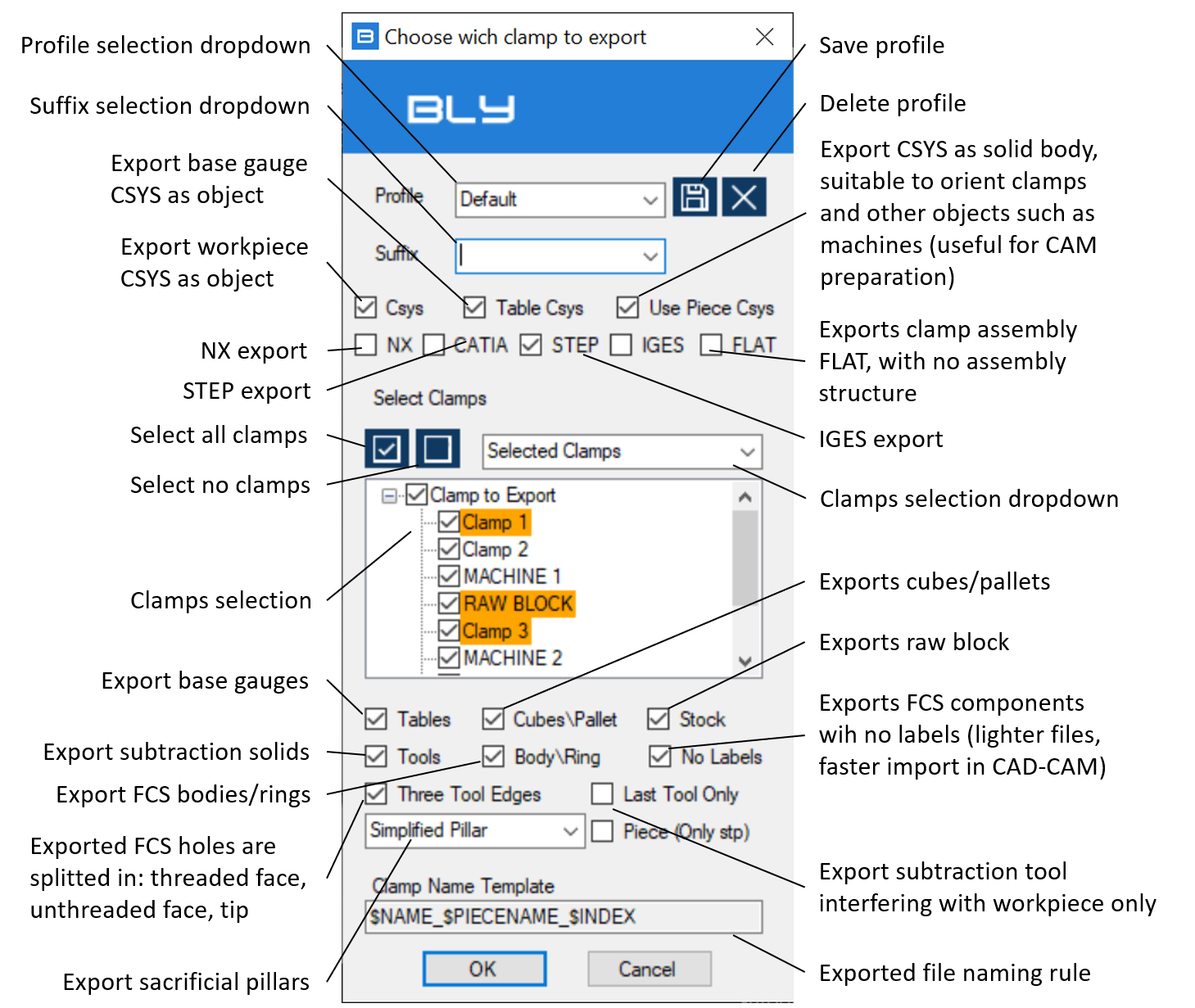
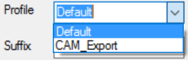
Profile selection dropdow: export configurations can be saved for further usage in profiles. This dropdown lists the available profiles
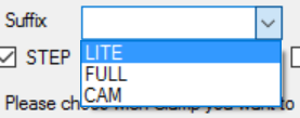
Suffix selection dropdow: clamping components can be exported in different versions than the original model (see below for more details), labeled with suffix. This dropdown lists the available suffix
Three tool edges: Guideline's tool models have tools split in 3 faces, to split thread from the core when subtracted in CAD. However, you may want to change the thread or create it full face: turning off this option will create a one-face tool
Exported file naming rule: Guideline 4.0's names the exported file following the naming convention displayed in that record. The convention can be set into Advanced Settings' GL tab (see Advanced settings: GL).
Export Workpiece (STEP only)
Should original workpiece open from a STEP file, exported clamp can add it to the assembly, in order to have it included when opened by Guideline 4.0 or 3D sofware that support this feature.
Technically speaking, Guideline 4.0 stores the original STEP file's path into the .bly file. When exports clamps, it is possible to add this information to the STEP file generated, which will "know" where the original workpiece's STEP file is in the file system. Opening the exported clamp with Guideline 4.0 will result into opening the clamp assembly (with FCS components) and the workpiece will be added into the correct position.
Other CAD or CAM system may support this functionality and add the workpiece as well, completing the clamps automatically: check with your sw provider for support.
Suffix
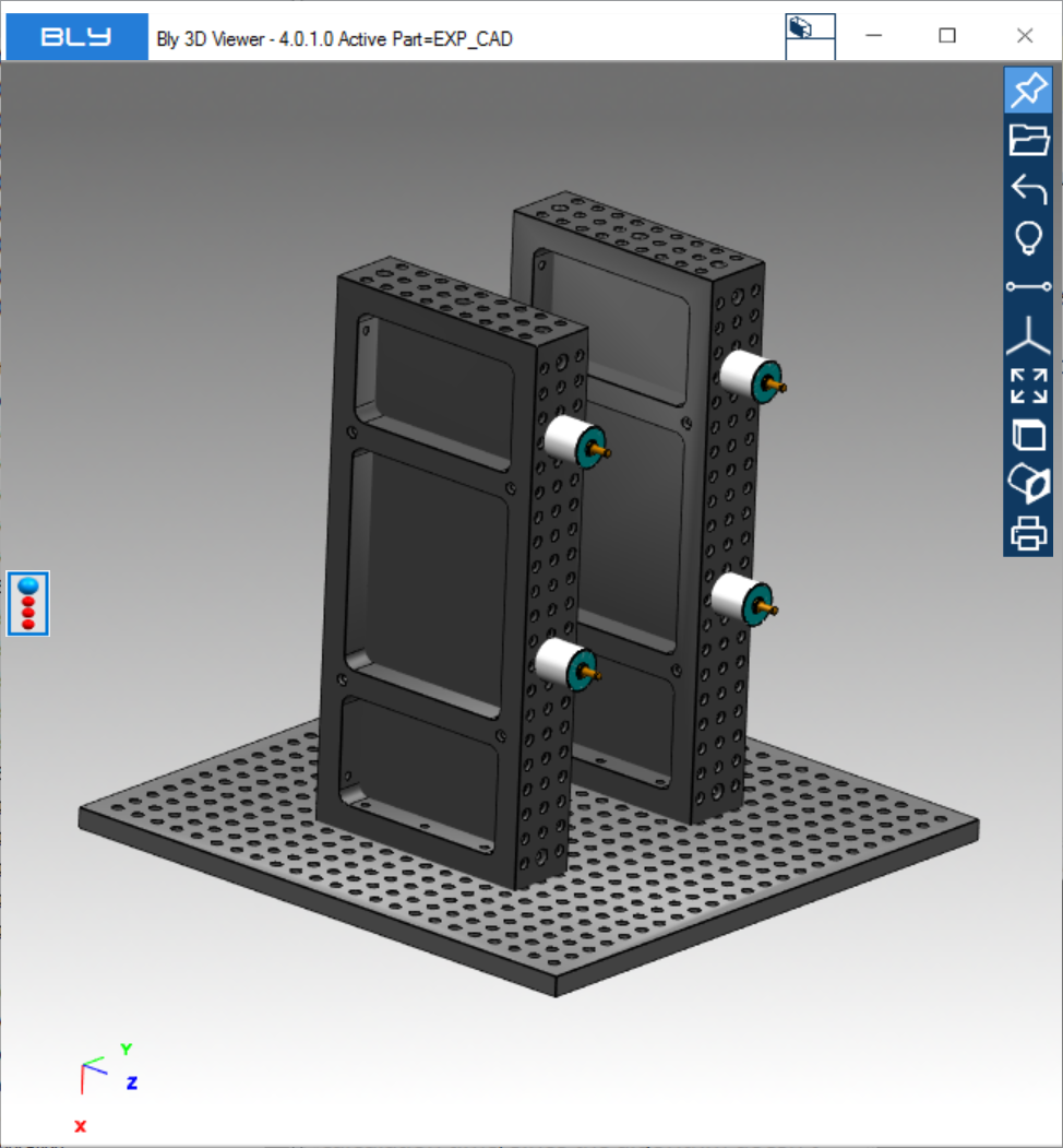
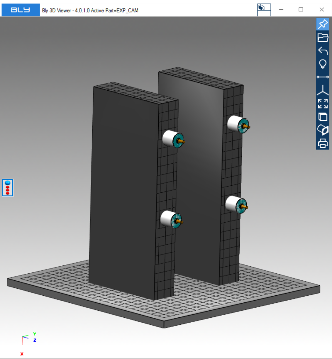
Guideline 4.0's component library can have multiple calmping component versions (alias) for export to STEP/IGES: this way it is possible to generate different 3D models for different usage.
Typical case is CAM, whose models are provided by default and which benefits from simplified tables with no holes: that shrinks the calculation time, since the algorithm doesn't have to analyse holes' surfaces.
Export and import time can be greatly improved too, since the models are much lighter.
For more details on how to create alias, please see chapt. Base gauges, shoulders, cubes, pallets, third-point arms, machines.
Layer management
Elements in exported STEP and IGES files can be placed on desired layers in 2 ways:
1) by default, Guideline 4.0 keeps elements as they are into the component library. Standard library contains all geometry on layer 1 and so have the exported clamps. Any modifications in CUSTOM library will be reflected in exported clamps;
2) in [GUIDELINE_INSTALLATION_DIRECTORY]\ClampComponents\Data there is a file named "LayerSpecs_to_change.txt", containing the assigned layer by object type. User can open this file and change the layer assigned by each object type. Renaming it to "LayerSpecs.txt", clamps' objects will be exported as defined. If this file will then be renamed or cancelled, Guideline 4.0 will use layers as set in the library.
Restarting Guideline 4.0 is required for the modifications to take effects.
Export Sacrificial Pillars
The drop-down menu in the picture below contains the three options to export sacrificial pillars:
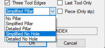
NO PILLAR: Pillars are not exported
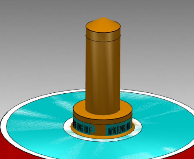
SIMPLIFIED PILLAR: Pillars are exported into fully-shaped solid bodies (cones or cylinders), 200 mm high. In the pillars, seats are subtracted already.
DETAILED PILLAR: Pillars are exported into trimmed NURBS. Seats are modelled too by NURBS.
SIMPLIFIED NO HOLE: Pillars are exported into fully-shaped solid bodies (cones or cylinders), 200 mm high, but with on seats are subtracted already.
DETAILED NO HOLE: Pillars are exported into trimmed NURBS, but with no seats.
The choice between the options above must be taken considering the subsequent steps to be taken (possibility to make a boolean operation, 3D software supporting solids ect.). Also, some 3D CAD or CAM do not support face topology (cylinders and cones), requiring them to be converted into NURBS.
Sacrificial pillars can be eported with specific color settings: in "LayerSpecs_to_change.txt", the attribute PillarColor can take any RGB values, which will be applied to all faces. Default is 1,1,1 (white).
Restarting Guideline 4.0 is required for the modifications to take effects.
Export to NX
This option defines the profile to be used for export towards NX definition. Since the target for NX export is the create subtractions, related settings are forced on and cannot be turned off
Settings must be then saved into a profile: that specifc profile can then be set into Advanced Settings (see Advanced settings: GL, GL to NX Setting Profile) and will be applied in interoperability #2 function (see Guideline-NX interoperability #2: ON-LINE).
Created with the Personal Edition of HelpNDoc: Easy EPub and documentation editor