Base gauges, shoulders, cubes, pallets, third-point arms, machines
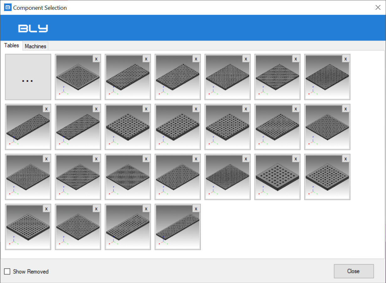
Base gauges can be accessed while creating new clamps and when replacing base gauges: in this occurrences, base gauge selection window opens and shows all the available tables.
Watch an example in this VIDEO.
Remove table(s)
To remove one table form the library, press ![]() from the related thumbnail: a confirmation message will appear:
from the related thumbnail: a confirmation message will appear:
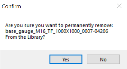
After pressing "Yes", the thumbnail will disappear, meaning that the table is not available anymore. However, the file is not permanently deleted and can be recalled if needed: thicking the "Show Removed" option at the bottom of the window will display all the tables previously removed from the library
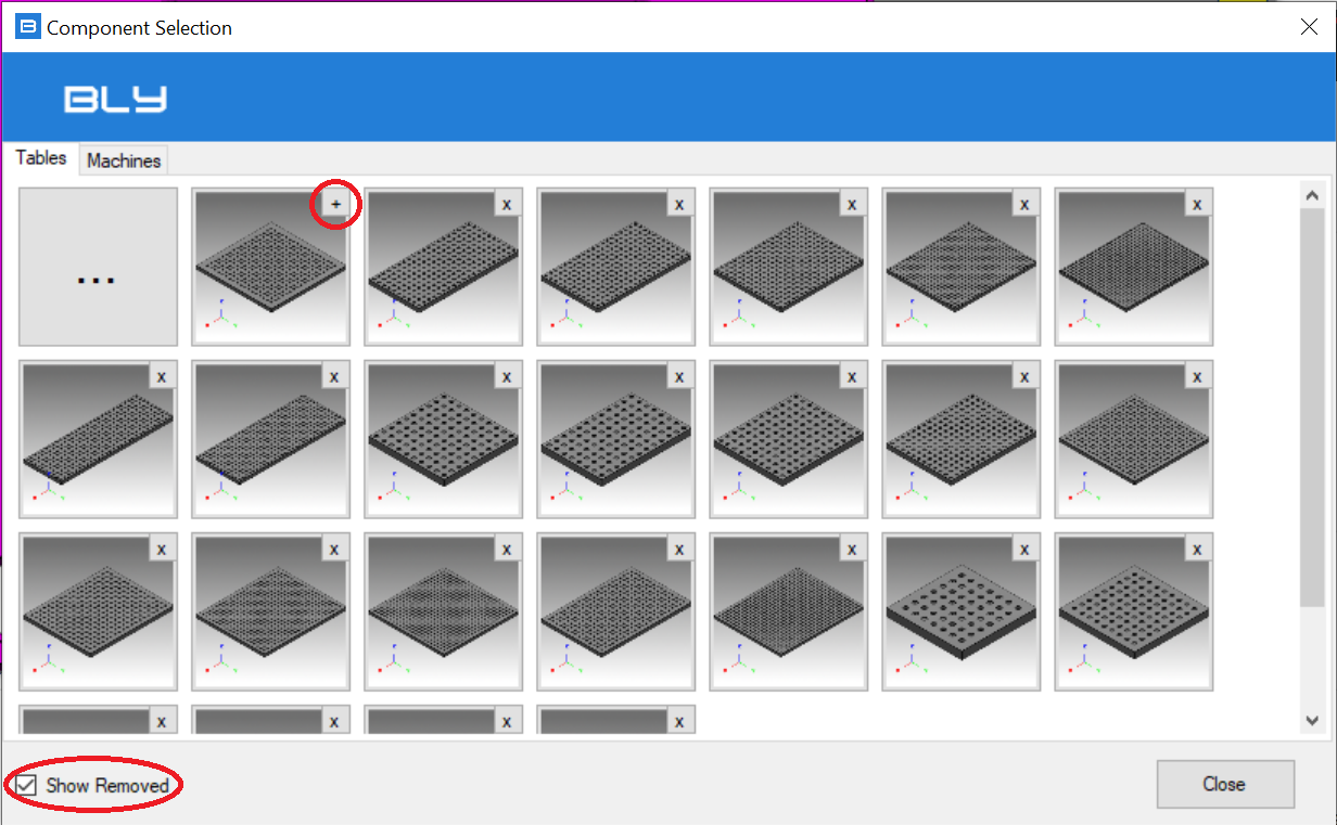
On the thumbail there is a  icon: pressing it will add the table back to the library.
As soon as a table is removed, Guideline 4.0 creates a text file in [GUIDELINE_INSTALLATION_DIRECTORY]\FCSSYSTEM named "ExcludedComponents.txt": it will list the removed tables and can be transferred between Guideline 4.0 installations to propagate library settings.
Add table
To add a custom component, press ![]() and choose its 3D model's STEP file from the file system.
and choose its 3D model's STEP file from the file system.
The model must have the holes with FCS standard dimensions (thread, counterbore, pitch).
Once selected, the table can be placed in the working clamp only or in the library choosing the related option from the window.
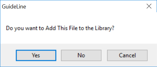
Pressin "Yes", Guideline 4.0 will insert the table to the clamp and will add the 3D model's STEP file to the [GUIDELINE_INSTALLATION_DIRECTORY]\CUSTOM\TABLES folder, making it available for future reusage. At the same time, Guideline 4.0 will generate the additional files needed (.bly,.jpg, .bmp). Simplified representations (i.e. CAM) must be separately created and manually added to the same folder (see Simplified models (CAM) paragraph below).
Other components (cubes, shoulders, pallets, third-point arms)
Shoulders, cubes, pallets, third-point arms and machines library can be accessed by "Add New Component To The Current Clamp" button ![]() and follow the same process: custom components can be managed as described above for the base gauges.
and follow the same process: custom components can be managed as described above for the base gauges.
IMPORTANT NOTICE: The 3D models must be in STEP file format, containing the table with holes with the proper dimensions for FCS System, with particular regards to counterbores diameter and depth. Please, refer to FCS catalog or contact BCK Solutions for further details on FCS holes geometry. Multiple solids are allowed (i.e. multiple base gauges, machine tables), although not strictly necessary.
Simplified models (CAM)
As explained in Export Clamp chapter, Guideline 4.0 can export modified FCS components (typically simplified with no holes and small details like chamfers and blends): this can significantly increase overall efficiency, for example speeding up translation as well as transfer to CAM pre-set models for campath design (typically removing holes).
Guideline 4.0 comes with CAM alias for the complete FCS catalog, but other alias can be created (or can replace the ones provided). Those alias must be created in STEP format and then saved in the appropriate folder with this naming convention: [ORIGINAL_FILE_NAME]+[_SUFFIX].stp
Example: if an alias SIMPLE is needed for table "base_gauge_M16_TR_1000X1000_0007-04304", a STEP file with the desired geometry must be saved as "base_gauge_M16_TR_1000X1000_0007-04304_SIMPLE.stp" in the \TABLES folder. Once ready, it can be selected for export.
Siemens NX Integration
Similarly, the new model can be transferred to Siemens NX (see SIEMENS NX INTEGRATION): for the example above, an NX file called "base_gauge_M16_TR_1000X1000_0007-04304.prt" must be saved in \TABLES folder.
Dassault Systémes CATIA V5 Integration
Similarly, the new model can be transferred to DS CATIA V% (see DASSAULT SYSTEMES CATIA v5 INTEGRATION ): for the example above, a CATIA file called "base_gauge_M16_TR_1000X1000_0007-04304.CATPart" must be saved in \TABLES folder.
Created with the Personal Edition of HelpNDoc: Qt Help documentation made easy