Clamp components (bodies, rings)
Bodies and rings have a separate environment to manage their library, since their availability influences the stacks' algorithm.
Guideline 4.0 comes with 3 libraries embedded, one fixed (named "FULL") and 2 customisable and removable. In addition, user can add further libraries to better reflect company's inventory.
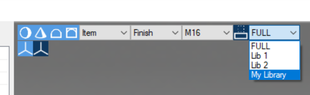
The active library can be selected for the specific drop-down list at the top of the screen:
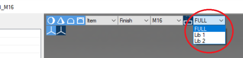
"FULL" is a fixed library: it contains the full FCS catalog with 1000 elements each, enough to satisfy any possible combinations.
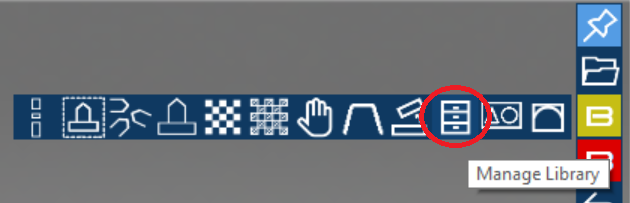
The other two are customizable: once active, they can be modified pressing "Manage Library" (see below)
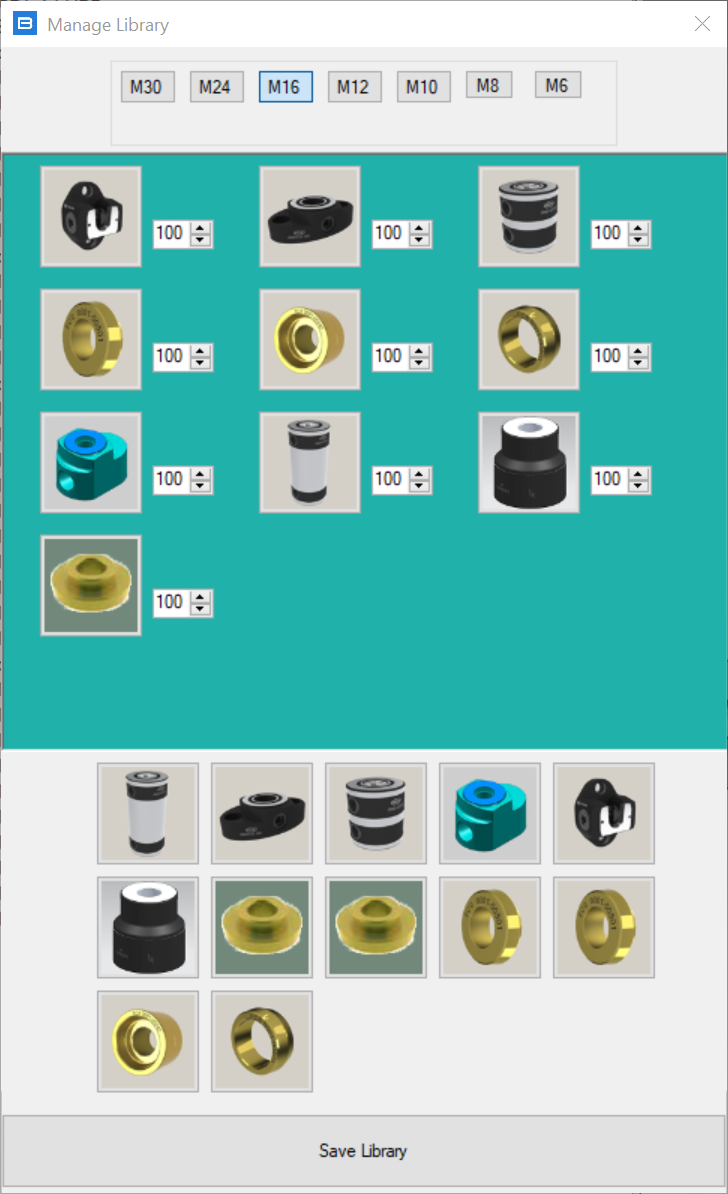
Manage Library shows all the components available to active Guideline's library, divided by size.
User can drag out and adjust component's quantity to list only component's available in the company. Components can be added back dragging them in from the list at the bottom and quantity can be adjusted with the arrow buttons or typing the number in each field. To remove one component, set its quantity to "0".
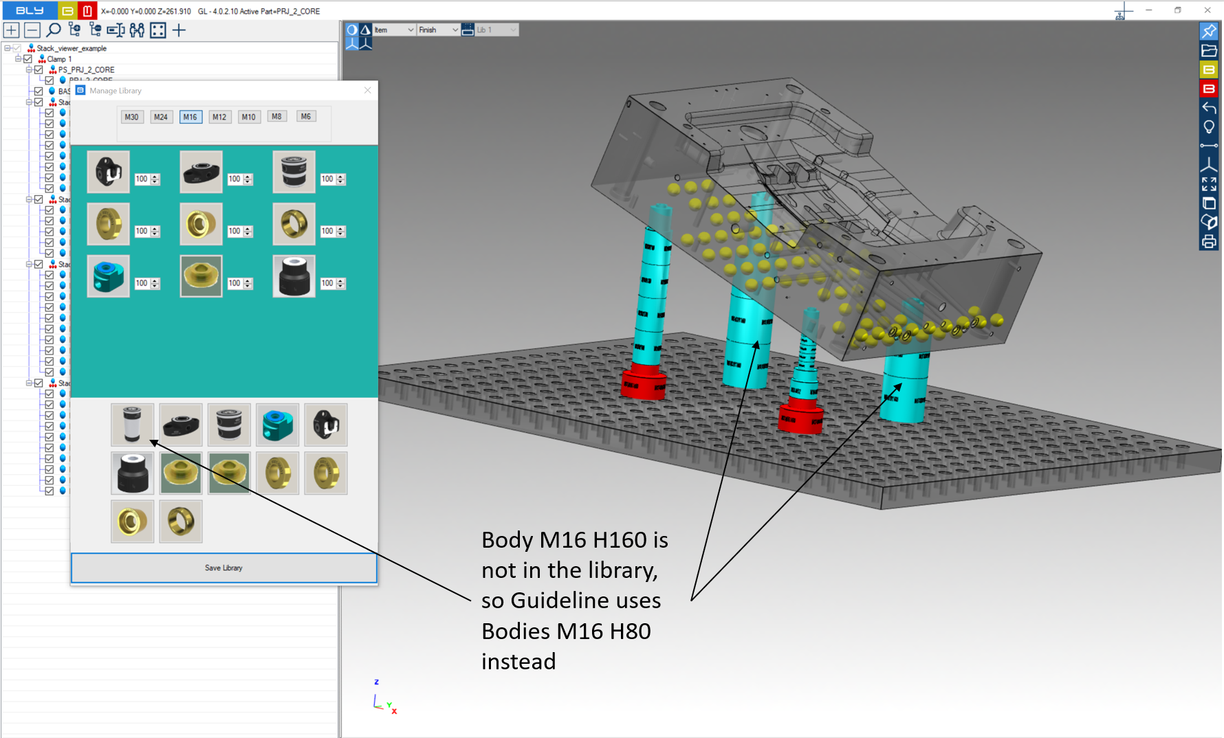
Once library is modifications are saved pressing "Save Library" button, immediately Guideline modifies stacks present already reflecting that settings: in particular, components not in the library are not used in the stack cration,
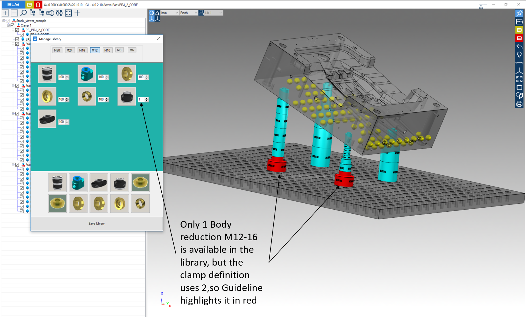
while a violation of the quantity highlights in red the component(s) affected.
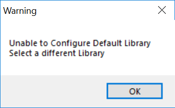
Trying to modify the "Full FCS" library will diplay the following error message:
Finally, Guideline 4.0 will set as default the last library set before closing the sw (unless Bly3DSettings.txt is in place, see Export user's settings).
A video showing an example can be seen here.
It is possible to remove or add customisable libraries following this procedure:
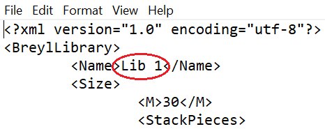
- in \\GuideLine V4\Misc directory, copy and paste Lib1.txt file and remane it as desired (i.e. mylibrary.txt)
- open Libraries.txt and add the library file name (mylibrary.txt) or remove the one(s) you do not want to use anymore;
- open the library file just created (mylibrary.txt) and change its name from "Lib 1" with the one you want to display in Guideline 4.0 (i.e. My Library)
- restart Guideline 4.0: the new library will be listed in the drop down menu
Library can be then customised to reflect the inventory.
Create a new subtraction tool
Standard FCS catalog's bodies’ and tools’ 3D models are placed in \GuideLine V4\FCSSystem folder, divided by size in the subfolders. In \GuideLine V4\CUSTOM folder is replicated the same stucture: new and modified components must be saved in the approriate subfolder of CUSTOM, keeping the same file name. Guideline 4.0 will load any component from CUSTOM folders first and then go to FCSSystem to load the remaining.
IMPORTANT: do not remove original files form FCSSystem subfolders. They will be constantly maintained and updated when necessary by new releases.
EXAMPLE OF TOOL'S MODIFICATION
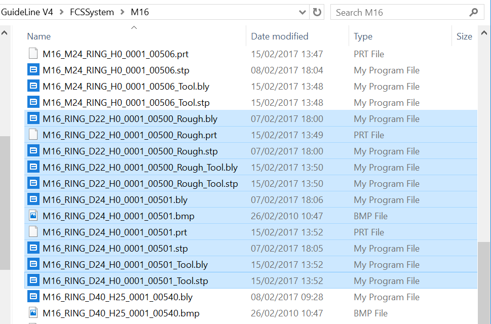
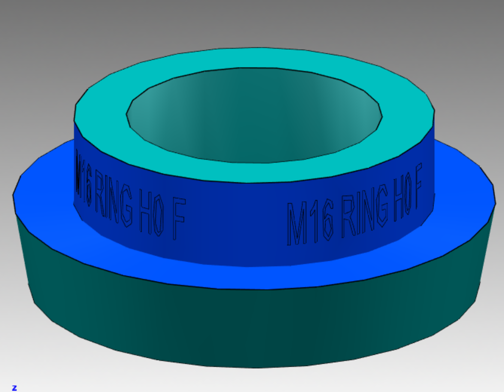
In the picture below, the M16 H0 ring (FCS catalogue codes: 0001_00500 roughing, 0001_00501 finishing) is highlighted as example.
For any ring, the there are 11 files associated:
- A .bly file containing the ring's 3D model, roughing size used in Guideline (M16_RING_D22_H0_0001_00500_Rough.bly);
- A .prt file for Siemens NX containing the ring's and seat's 3D model, roughing size (M16_RING_D22_H0_0001_00500_Rough.prt);
- A step file used for translating the ring's geometry, roughing size (M16_RING_D22_H0_0001_00500_Rough.stp);
- A .bly file containing the seat's 3D model, roughing size used in Guideline (M16_RING_D22_H0_0001_00500_Rough_Tool.bly);
- A step file used for translating the seat, roughing size (M16_RING_D22_H0_0001_00500_Rough_Tool.stp);
- A .bly file containing the ring's 3D model, finishing size used in Guideline (M16_RING_D24_H0_0001_00501.bly);
- A bitmap (M16_RING_D24_H0_0001_00501.bmp);
- A .prt file for Siemens NX containing the the ring's and seat's 3D model, finishing size (M16_RING_D24_H0_0001_00501.prt);
- A step file used for translating the ring's geometry, finishing size (M16_RING_D24_H0_0001_00501.stp);
- A .bly file containing the seat's 3D model, finishing size used in Guideline (M16_RING_D24_H0_0001_00501_Tool.bly);
- A step file used for translating the seat's geometry, finishing size (M16_RING_D24_H0_0001_00501_Tool.stp);
Procedure
In order to modify the geometry of tools in the library, you should first create 3D models of the desired seats: you can do it using any CAD system. A good starting point can be import the existing geometry in a CAD and modify it. Be sure to respect the nominal dimensions of FCS System and the original CSYS.
In particular, seats must have the counterbore a little larger than nominal diameter: reccomended clearance is 0,02 mm on diameter. This can be either managed in design or in production: in the first case, seat's 3D models must have diameter 0,02 mm greater than nominal, otherwise model them at nominal diameter and adjust the dimension in CAM/workshop.
Once you have the modified 3D model ready, please do the following:
- Create 2 solid bodies for:
- The ring, standard or modified if the case;
- A body resulting from the union between the ring + the seat. This can be created with a boolean union or modeling it from scratch. Removing details (chamfers, blends, holes) from the model is a good idea to minimize file size and maximise performance;
- Create one STEP file for each solids above, named as the ring and related tool in library (M16_RING_D24_H0_0001_00501.stp and M16_RING_D24_H0_0001_00501_Tool.stp in our example). Place them in the appropriate CUSTOM library sub-folder (\GuideLine V4\CUSTOM\M16 in our example);
- Use Guideline 4.0 to save both .bly files containing the ring and the tool body respectively. Name them as convention (M16_RING_D24_H0_0001_00501.bly and M16_RING_D24_H0_0001_00501_Tool.bly in the example) and place them in the proper folder in libray (\GuideLine V4\CUSTOM\M16 in the example);
- Repeat the process and create files for roughing size, add "_Rough" and the FCS code in the names (M16_RING_D24_H0_0001_00500_Rough.stp, M16_RING_D24_H0_0001_00500_Rough.bly, M16_RING_D24_H0_0001_00500_Rough_Tool.stp and M16_RING_D24_H0_0001_00500_Rough_Tool.bly in the example) and place them in the proper folder in libray (\GuideLine V4\CUSTOM\M16 in the example);
- OPTIONAL: if you use Siemens NX with Guideline integration, you should create the .prt files for finishing a roughing, name them as convention (M16_RING_D22_H0_0001_00500_Rough.prt and M16_RING_D24_H0_0001_00501.prt) and place them in the same directory.
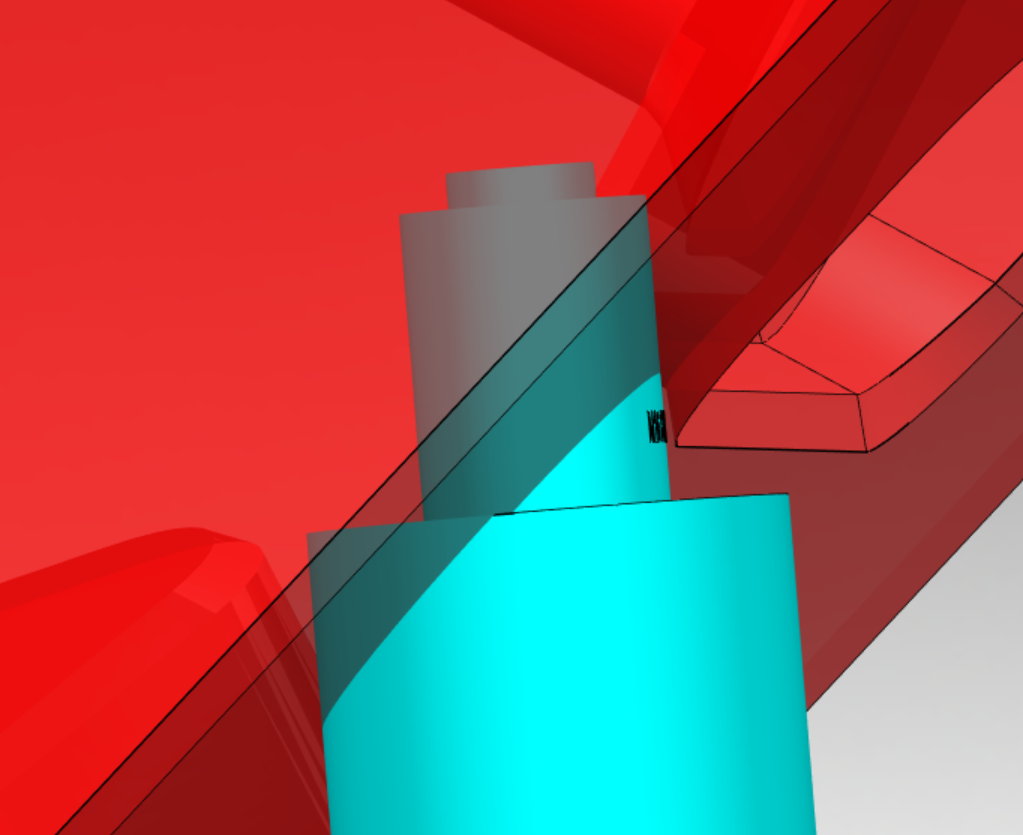
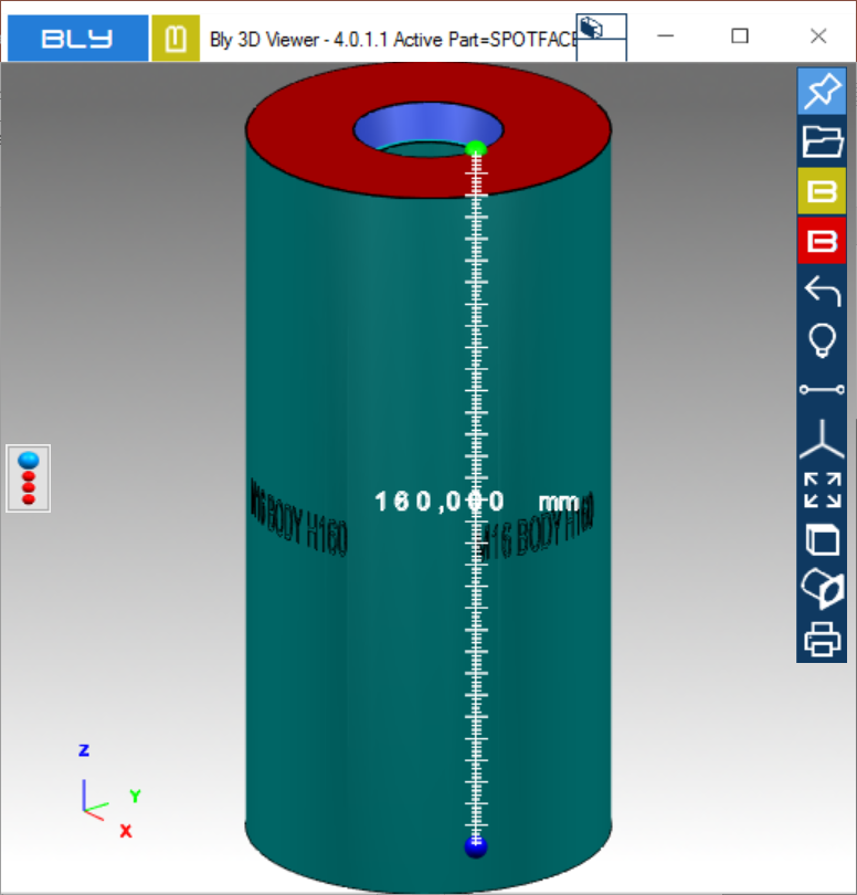
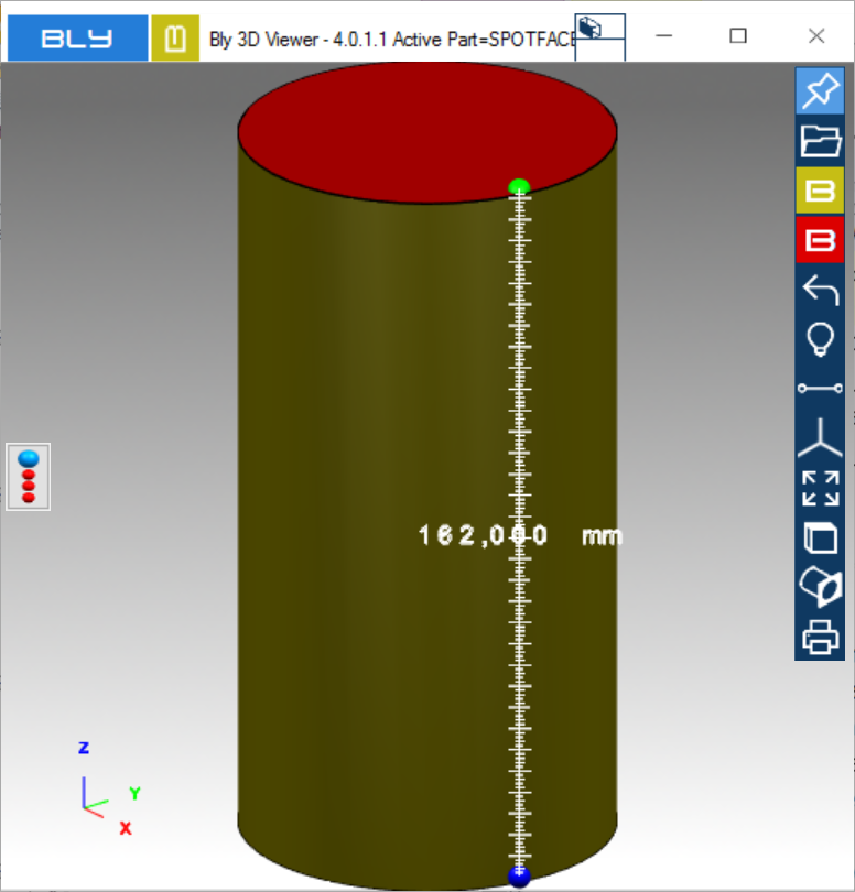
Subtraction Bodies
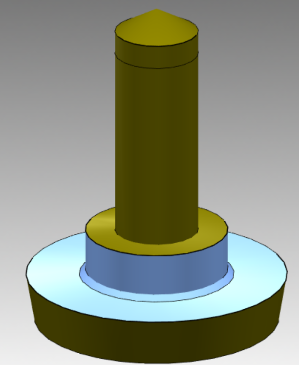
FCS components other than rings may require a spotface to accomodate them in specific clamps. Guideline provides the spotface's geometry using specific solid bodies contained in dedicated step files exported when needed (see examples in the pictures aside): the named of those bodies is "Subtraction Bodies" and can be one for small rings (with offset diameter) or two for bodies (one with larger diameter and one having both larger diameter and height).
Those subtraction bodies can be customised following the procedures above, always respecting the name convention:
- "componentname_Tool" for subtraction body #1, both .bly and .stp
- "componentname_Tool_2" for subtraction body #2 both .bly and .stp