PHASE 1: Stacks placement
Watch a tutorial in this video
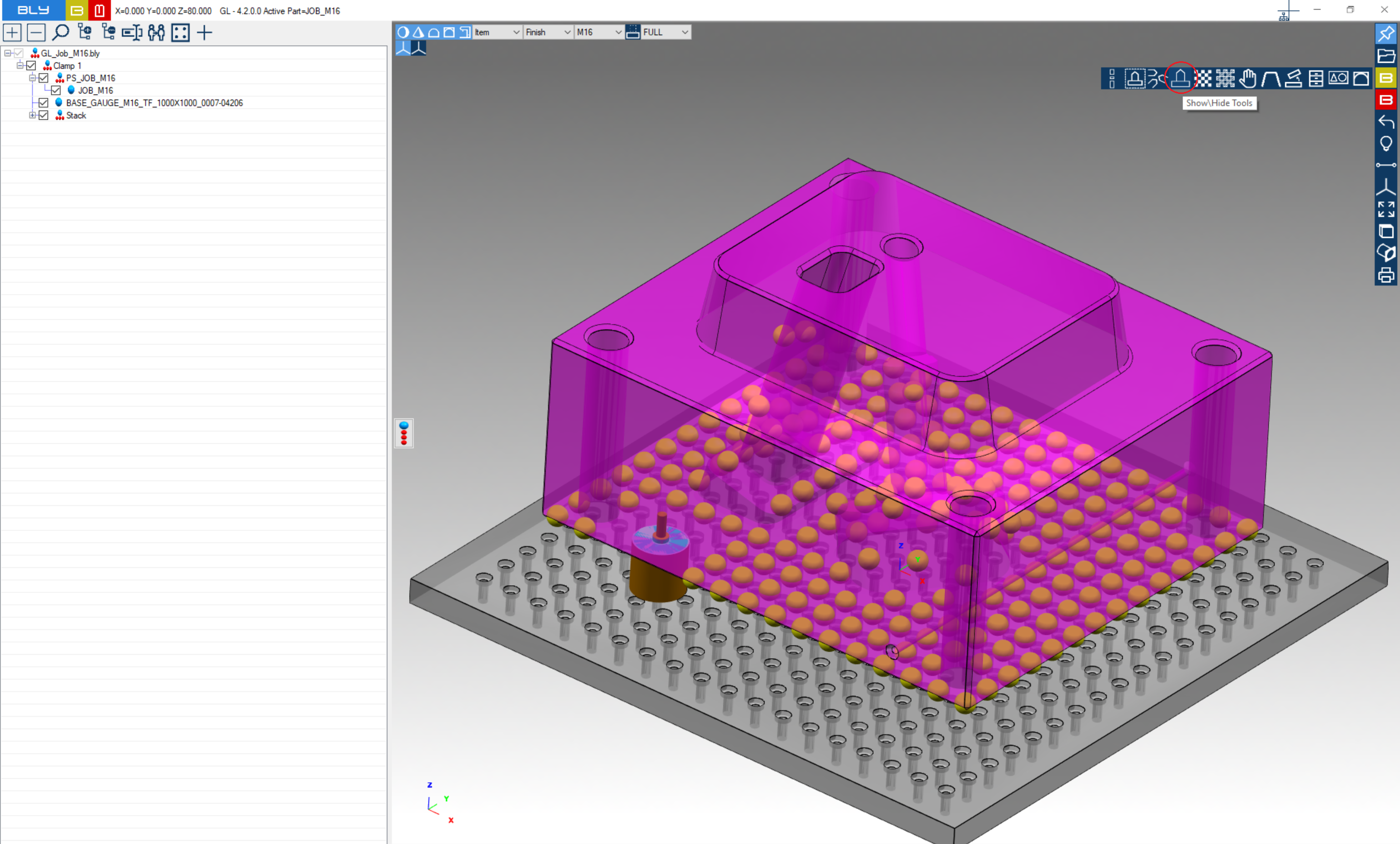
After selecting the base gauge, Guideline projects the placement holes from the table onto the job and represents them with yellow spheres.
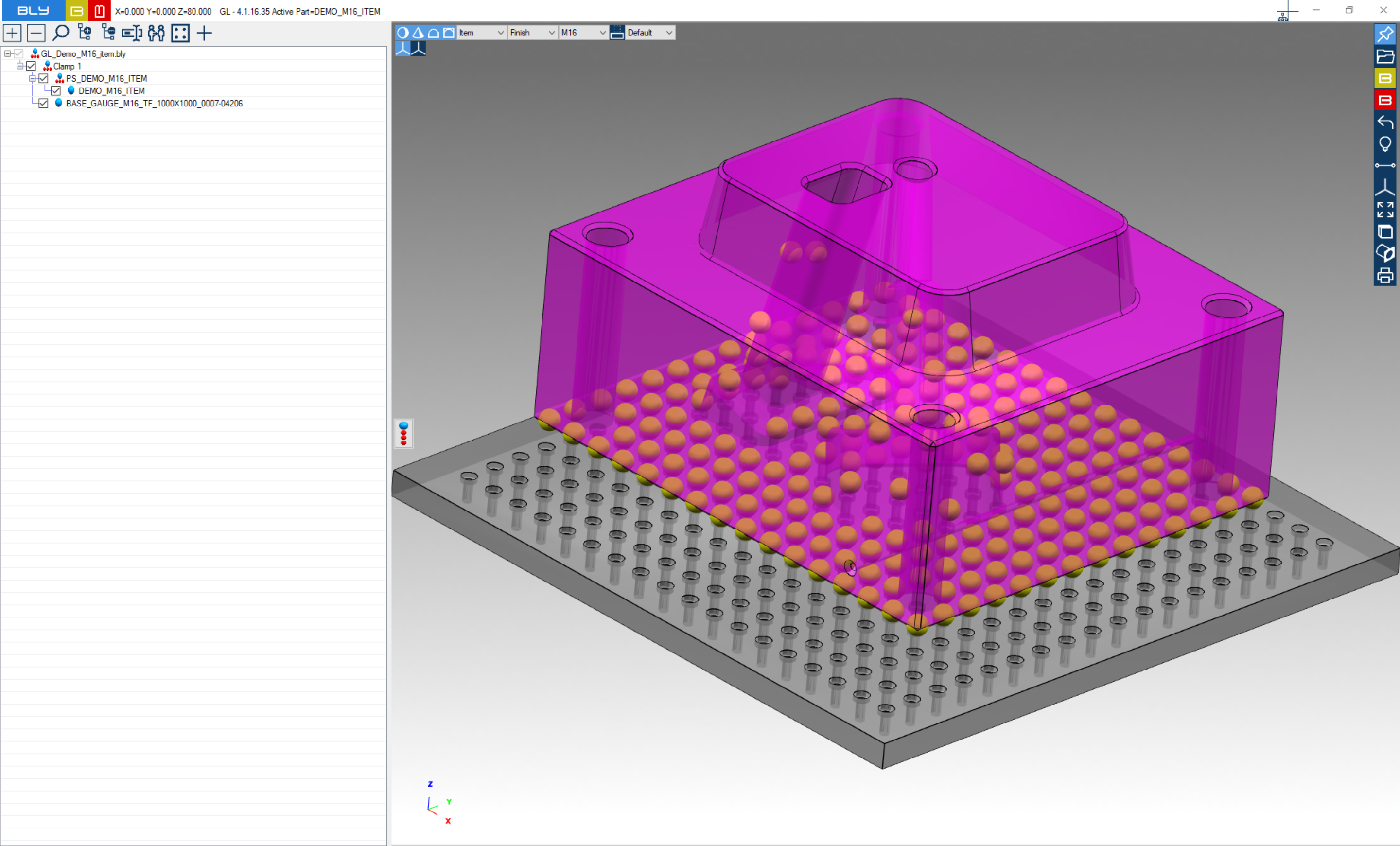
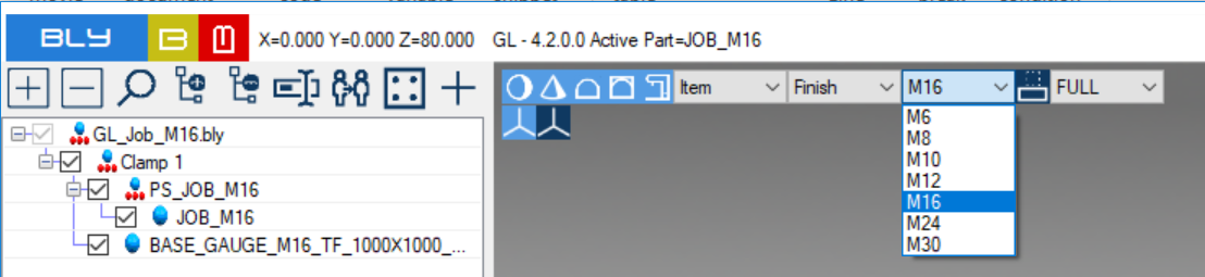
Before inserting the stacks, seat size must be selected (default M16), either from Piece Settings menu or te dropdown on top of the graphic area:
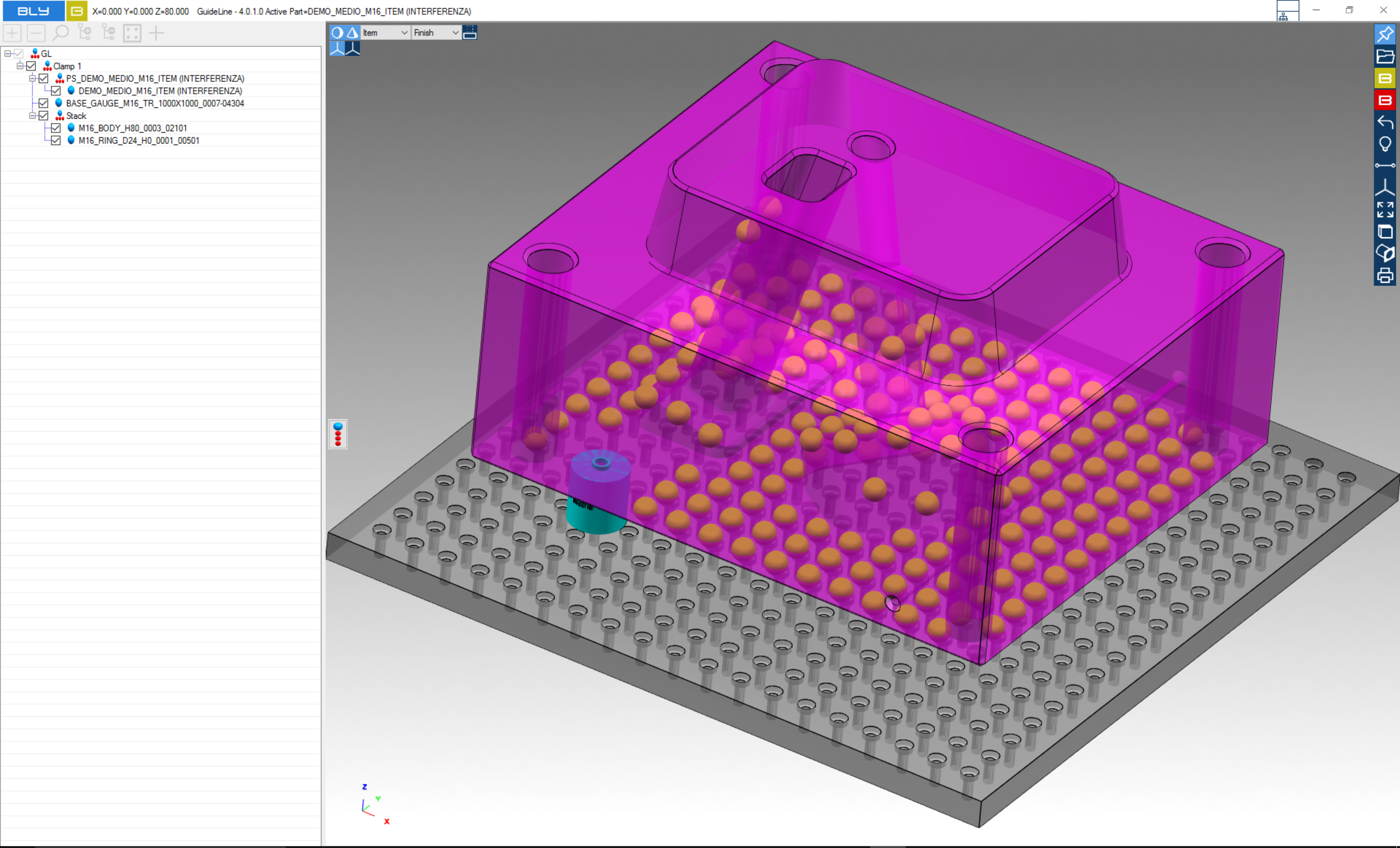
Clicking one of the spheres makes Guideline calculate the stack needed to keep the job in this position and it will place a stack
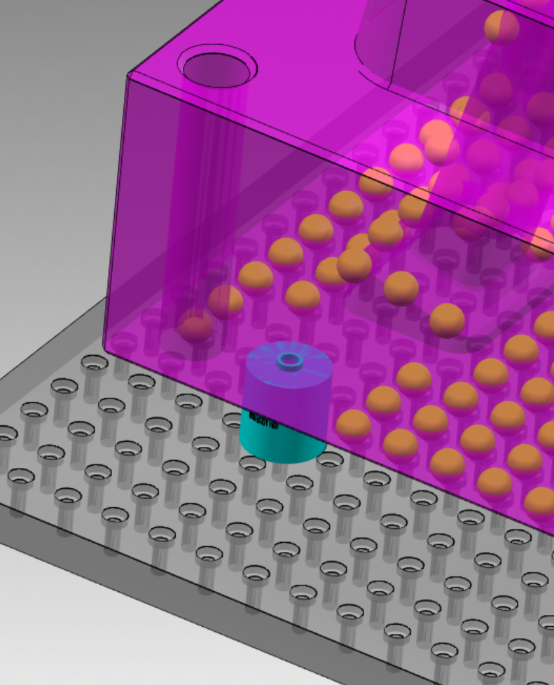
There is no limitation in the number of stacks that it is possible to create.
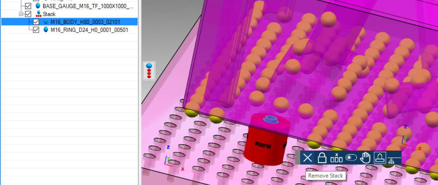
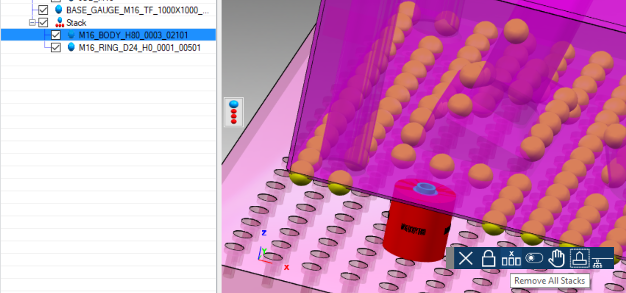
To delete the stack(s), click on one of those and select "Remove Stack" or "Remove All Stacks" from the contextual toolbar that displays
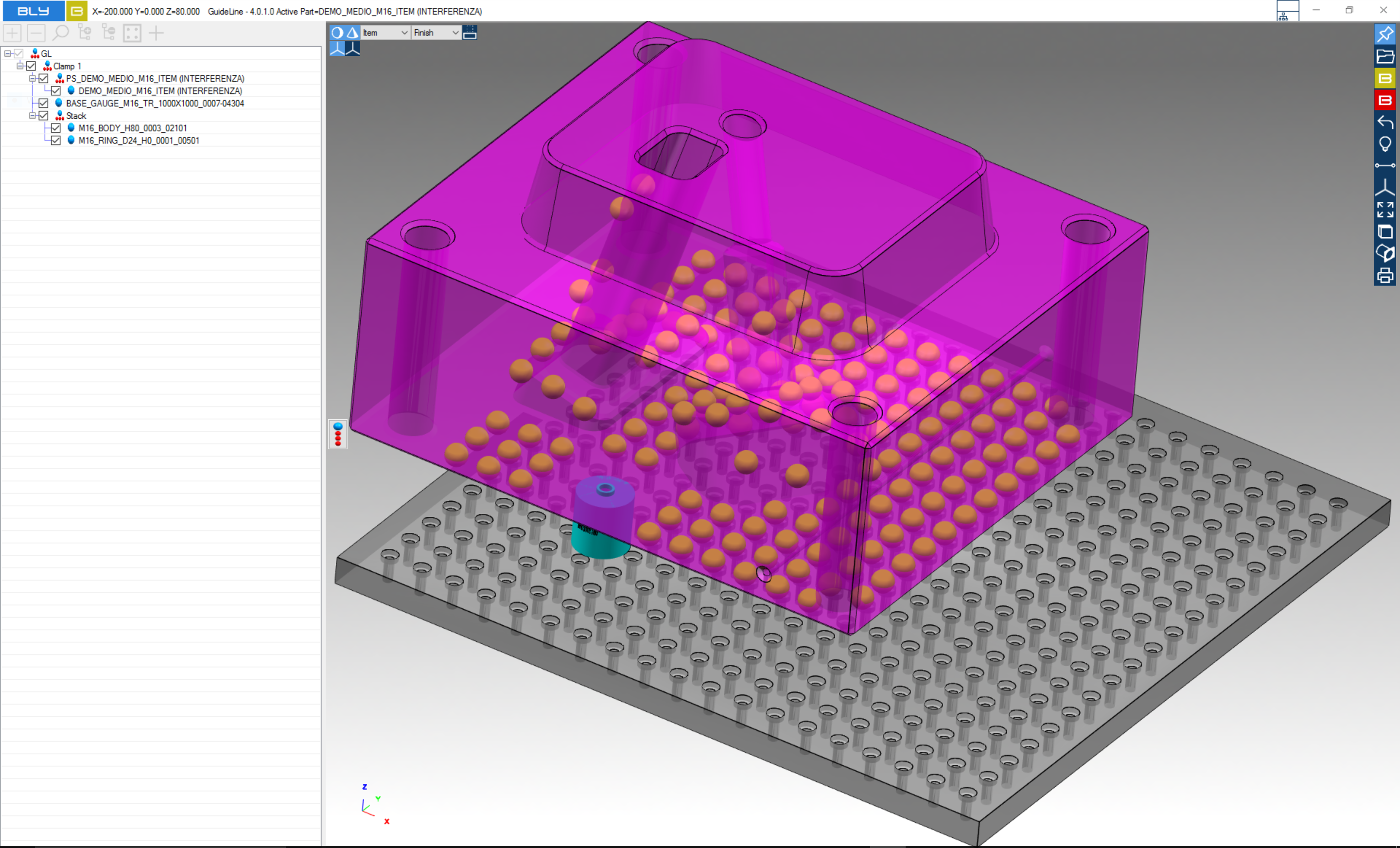
When the stacks are placed, the job's position can be varied: at this stage, the stack will remain still and the job will move over the stacks placed.
Please note that there is no rigid sequence to follow: user can place stacks and adjust the job's position anytime during the clamping design.

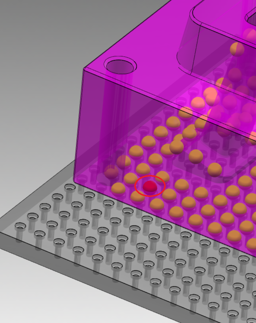
Using bodies "H40" series, it may be defined a postion that left them partially exposed out form the base gauge (see below).
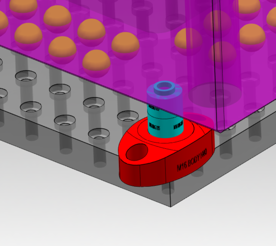
Although not necessarily a mistake, this configuration must be carefully evaluated when designing a clamp, since it can easily lead to machine head or tools crashes: therefore, once a sphere is selected and the stack requires a H40 body, Guideline 4.0 will automatically try to orient it to prevent the situation described: if this is not possible because of the lack of space, H40 body will be highligthed in red.
Seats geometry (tools)
Place a stack means automatically add the geometry of the FCS seats to the 3D model. Watch an example in this VIDEO
The sum of the geometry related to FCS seats (hole, countebore, thread and the spotfaces needed to accomodate the stacks in the job) are called in Guideline "Tools".
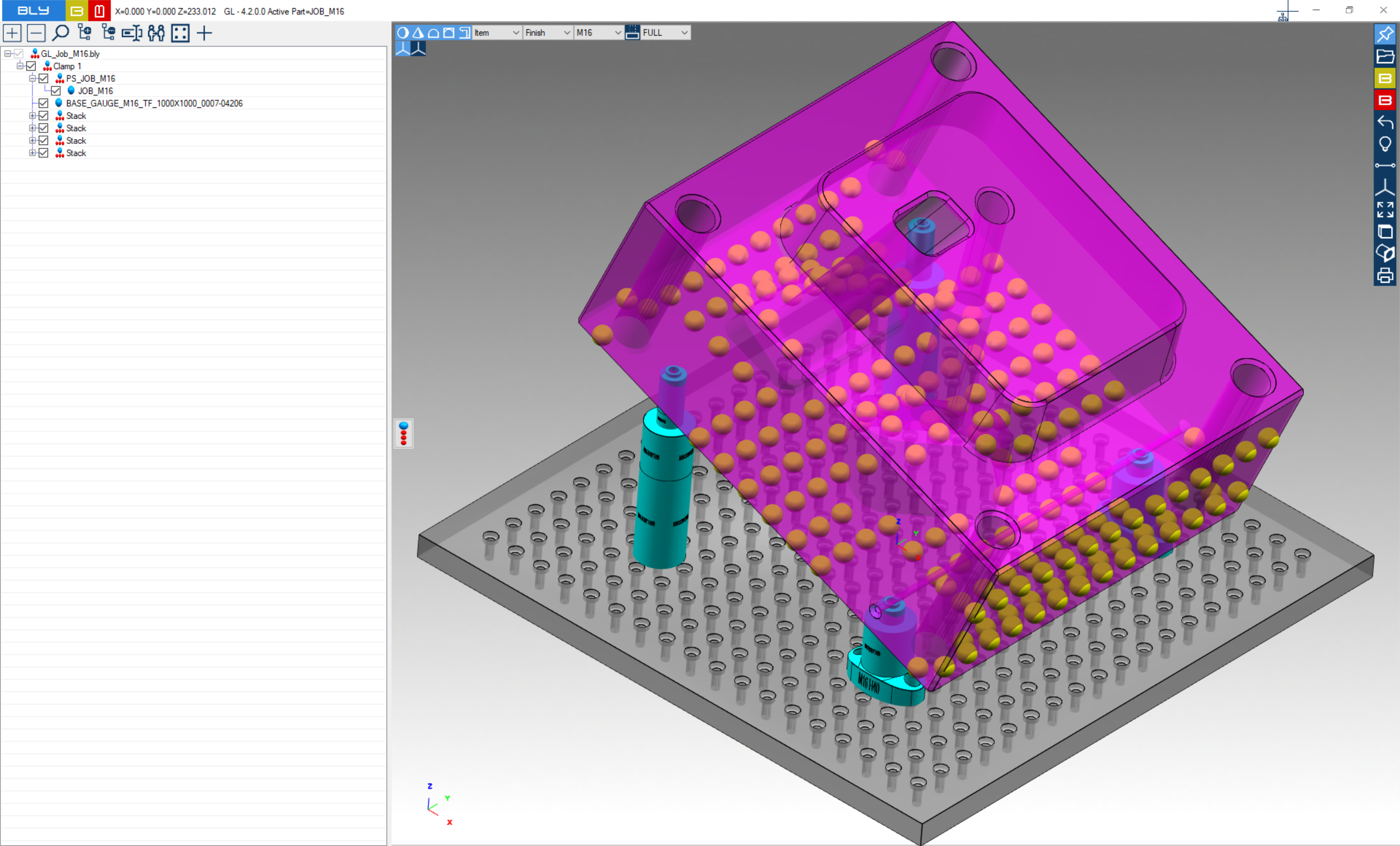
Tools can be displayed pressing "Show/Hide Tools" button.
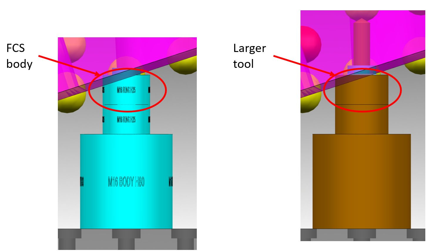
Should the geometry require the stacks penetrate into the job, Guideline provides larger 3D bodies in order to create appropriate spotfaces large enough to accomodate the breils.
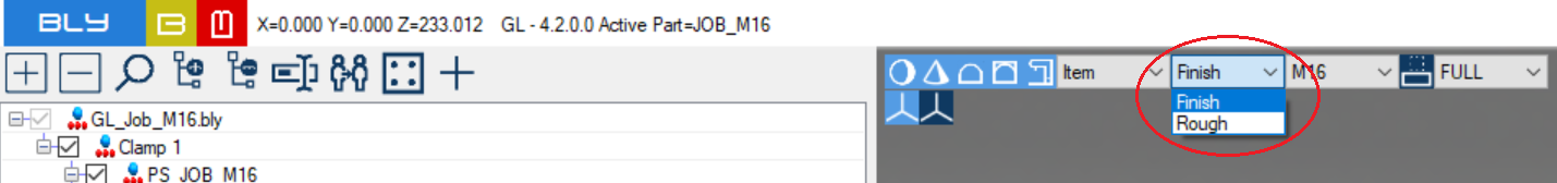
Ring size selection
FCS System define two sizes for each ring's dimensional class, Rough and Finish. This allow the compensation of deformations after thermal treatment, being the finishing ring larger than the roughing (i.e. for M16, finishing ring diameter is 24mm against 22mm for the roughing).
Ring size can be selected by the drop-down menu in the picture: stacks will be calculated placing the ring accordingly.
Created with the Personal Edition of HelpNDoc: Easily create PDF Help documents